
WeMos D1 ESP8266 Web Controlled Switch

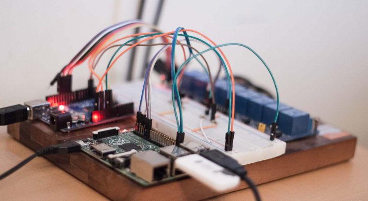
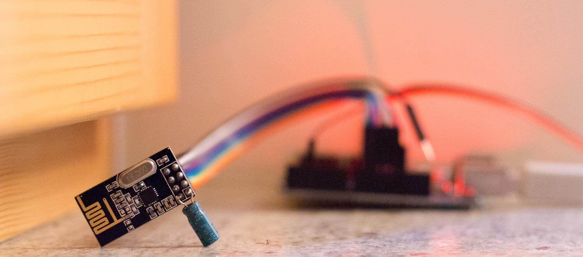
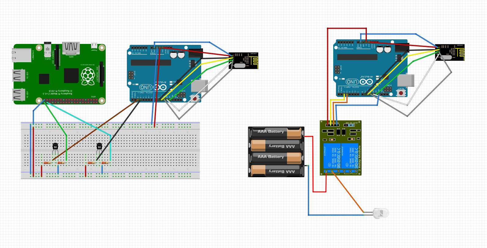
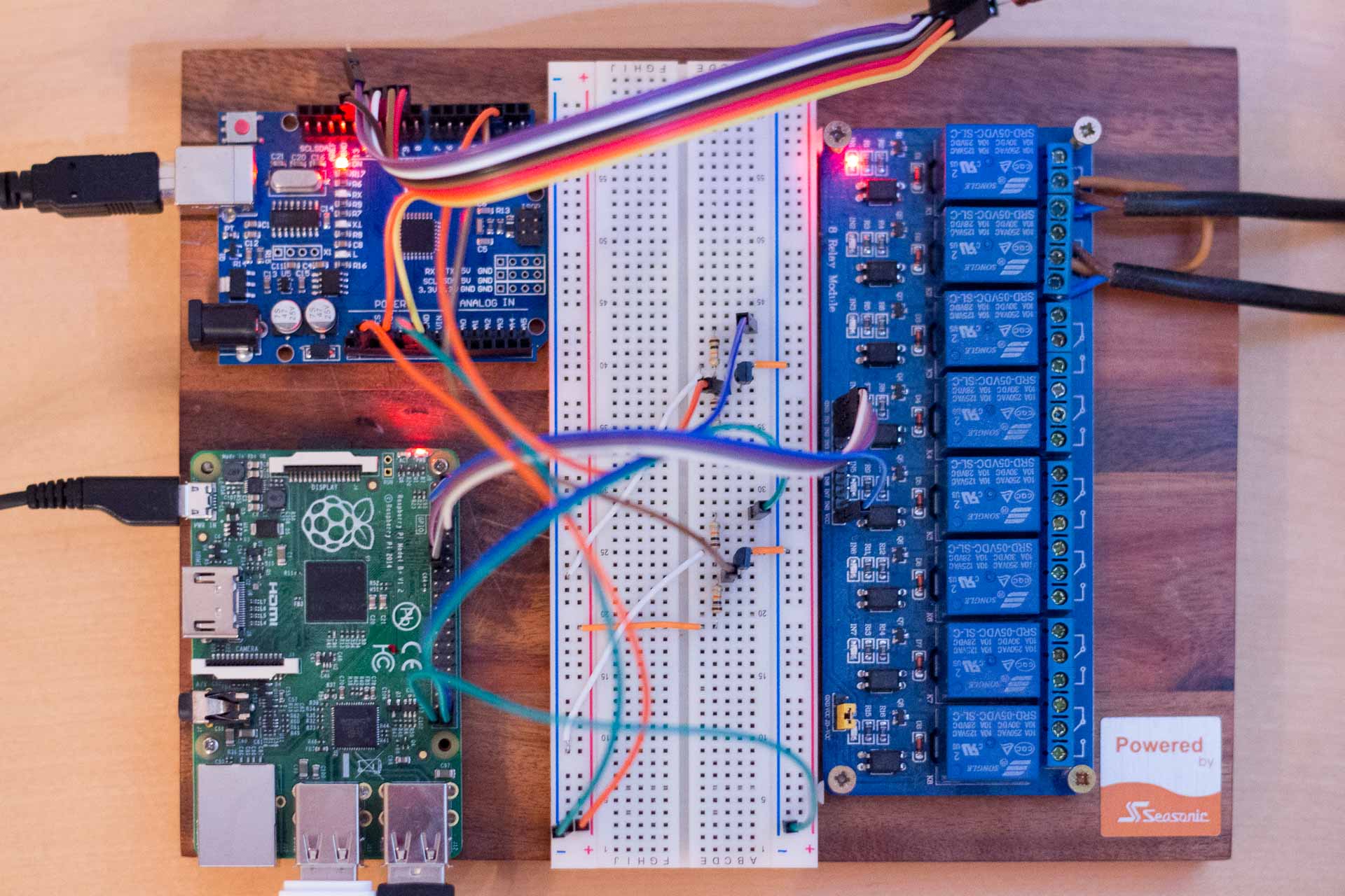
Last year I made Room automation with Raspberry Pi and few Arduinos for switching lights and air conditioner on and off using my phone. It required lots of components for accomplishing a simple task. The reason was that Arduino itself cannot connect to wifi and NRF24L01+ module doesn’t support TCP/IP protocol, so I needed Raspberry Pi for wifi connection. Also using new Raspberry Pi for each light switch is just too expensive. This time I used WeMos ESP8266.

ESP866 is an inexpensive Wifi Module for Arduino that supports 802.11 b/g/n protocols and it can also run Arduino code. There are multiple versions of this SOC. Some require serial to USB adapter for programming and some have micro USB port. They also vary by amount of GPIO ports and memory they have.

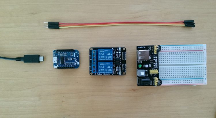
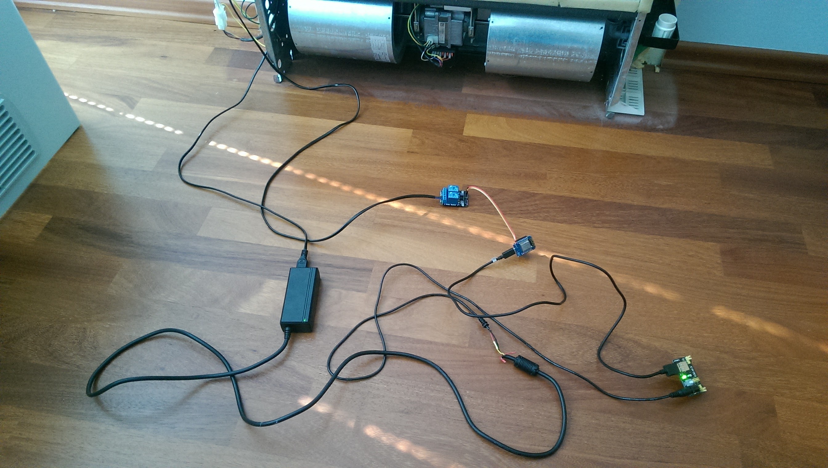
List of parts that I also used for this project:

  • WeMos D1 ESP8266
  • Relay module
  • MB102 Breadboard Power Supply Module
  • Old notebooks power adapter

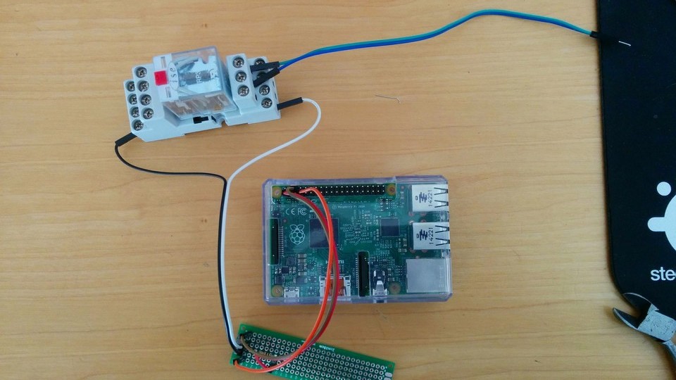
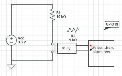
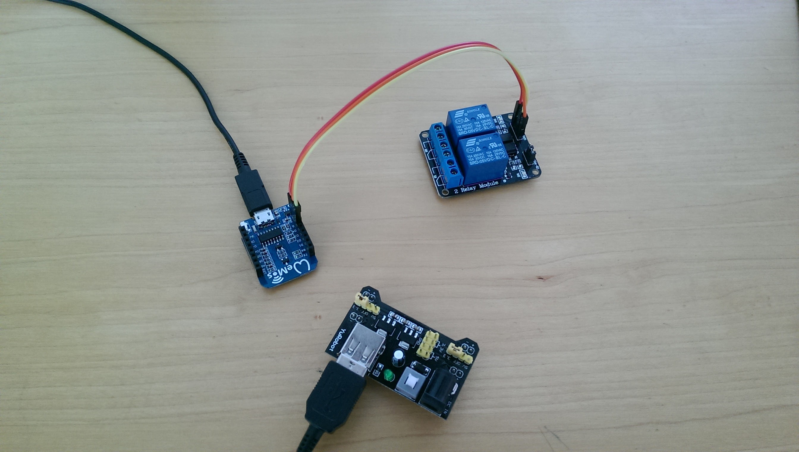
For assembly I connected notebook’s PSU to MB102 PSU module, MB102 to ESP8266 with USB cable and GPIO ports 0, 2 and ground on ESP8266 to Relay module.

ESP8266  WeMos
ESP8266 WeMos

I modified ESP8266 library example code and uploaded it on the WeMos ESP8266:

#include <ESP8266WiFi.h>

const char* ssid = "SSID";
const char* password = "wifi password";

// Create an instance of the server
// specify the port to listen on as an argument
WiFiServer server(80);

void setup() {
  Serial.begin(115200);
  delay(10);

  // prepare GPIO2
  pinMode(2, OUTPUT);
  digitalWrite(2, 0);
  
  // Connect to WiFi network
  Serial.println();
  Serial.println();
  Serial.print("Connecting to ");
  Serial.println(ssid);
  
  WiFi.begin(ssid, password);
  
  while (WiFi.status() != WL_CONNECTED) {
    delay(500);
    Serial.print(".");
  }
  Serial.println("");
  Serial.println("WiFi connected");
  
  // Start the server
  server.begin();
  Serial.println("Server started");

  // Print the IP address
  Serial.println(WiFi.localIP());
}

void loop() {
  // Check if a client has connected
  WiFiClient client = server.available();
  if (!client) {
    return;
  }
  
  // Wait until the client sends some data
  Serial.println("new client");
  while(!client.available()){
    delay(1);
  }
  
  // Read the first line of the request
  String req = client.readStringUntil('\r');
  Serial.println(req);
  client.flush();
  
  // Match the request
  int stat;
  if (req.indexOf("/gpio/0") != -1){
    digitalWrite(2, 0);
  }
  else if (req.indexOf("/gpio/1") != -1){
    digitalWrite(2, 1);
  }
  else if (req.indexOf("/status") != -1){
  }
  else {
    Serial.println("invalid request");
    client.stop();
    return;
  }

  // Set GPIO2 according to the request
  stat = digitalRead(2);
  
  client.flush();

  // Prepare the response
  String s = "HTTP/1.1 200 OK\r\nContent-Type: text/html\r\n\r\n<!DOCTYPE HTML>\r\n<html>\r\n";
  s += (stat)?"high":"low";
  s += "</html>\n";

  // Send the response to the client
  client.print(s);
  delay(1);
  Serial.println("Client disonnected");

  // The client will actually be disconnected 
  // when the function returns and 'client' object is detroyed
}

Module automatically connects to wifi when powered and receives an IP address from router (192.168.1.45 for example). It’s IP may change every time module disconnects from wifi, so I assigned it static IP address on my router.

You can switch GPIO on by sending HTML request to “http://[ESP8266s ip address]/gpio/0” and to turn it off “~/gpio/1”. This is done simply by visiting url in a web browser.
Disadvantage of the code from libraries example is that you can’t tell whether GPIO is on or off. I modified it so that html response includes info about its status when you visit ~/status.

Turning the air conditioner on by typing http://192.168.1.45/gpio/0 into a browser and making sure that it’s on or off by visiting http://192.168.1.45/status it’s not very practical, so I made a simple web interface and added it to my homes dashboard webpage.

<?php
 //get the GPIO status
 $html = file_get_contents('http://192.168.1.45/status');
 if (strpos($html, 'low') !== false) {
     $status = 0;
 }
 else {
   $status = 1;
 }
 

   if ($_POST["15"] == "1") {
     if ($status == 1) {
       file_get_contents('http://192.168.1.45/gpio/0');
       $status = 0;
     }
     elseif ($status == 0) {
       file_get_contents('http://192.168.1.45/gpio/1');
       $status = 1;
     }
   }
 ?>
 

 <!DOCTYPE html>
 <html lang="en">
 <head>
   <title>Switch</title>
   <meta charset="utf-8">
   <meta name="viewport" content="width=device-width, initial-scale=1">
   <link rel="stylesheet" href="https://maxcdn.bootstrapcdn.com/bootstrap/3.3.6/css/bootstrap.min.css">
 </head>
 <body>
 

 <div class="container">
   <div class="col-sm-3">
        <h3>Air conditioner</h3>
         <form  id="form" name="test" action="index.php" method="post">
           <input type="hidden" name="15" value="1"></input>
           <input type="submit" class="<?php if($status == 1) {print("btn btn-primary btn-lg btn-block");} else {print("btn btn-secondary btn-lg btn-block button");} ?>" value="<?php if($status == 1) {print("Turn Off");} else {print("Turn On");} ?>"></input>
         </form>
     </div>
     </div>
 </body>
 </html>

It displays a button with text “Turn on” or “Turn off” depending on the GPIOs current status. When you click it, it sends a html request to the module to change its GPIO state.
You can use as many ESP8266 modules as you want and manage them from a centralized web application.

Everything connected

Edit: Someone on Reddit requested code for managing multiple ESP8266s. So here is the code. To add new module, just add its IP address and name in the array.

<?php
 $devices = array(
     '192.168.1.66' => 'Light1',
     '192.168.1.45' => 'Light2',
     '192.168.1.47' => 'AirConditioner');
 

 $i = 0;
 foreach ($devices as $ip => $name) {
     $html = file_get_contents('http://' . $ip .'/status');
     if (strpos($html, 'low') !== false) {
         $status[$i] = 0;
     }
     else {
       $status[$i] = 1;
     }
     if ($_POST[$name] == "1") {
       if ($status[$i] == 1) {
         file_get_contents('http://'. $ip . '/gpio/0');
         $status[$i] = 0;
       }
       elseif ($status[$i] == 0) {
         file_get_contents('http://'. $ip . '/gpio/1');
         $status[$i] = 1;
       }
     }
   $i++;
 }
 ?>
  
 <!DOCTYPE html>
 <html lang="en">
 <head>
   <title>Switch Control Interface</title>
   <meta charset="utf-8">
   <meta name="viewport" content="width=device-width, initial-scale=1">
   <link rel="stylesheet" href="https://maxcdn.bootstrapcdn.com/bootstrap/3.3.6/css/bootstrap.min.css">
 </head>
 <body>
  
   <div class="container">
     <div class="col-sm-4">
     <h2>Switch Control Interface</h2>
     <? $i=0; foreach ($devices as $ip => $name) { ?>
        <h3><?echo $name;?></h3>
           <form  id="form" name="test" action="index.php" method="post">
             <input type="hidden" name="<? echo $name; ?>" value="1"></input>
           <input type="submit" class="<? print ($status == 1 ? 'btn btn-primary btn-lg btn-block' : 'btn btn-secondary btn-lg btn-block button');?>" value="<?php print ($status == 1 ? 'Turn Off' : 'Turn On');?>"></input>
           </form>
     <?php $i++; } ?>
     </div>
   </div>
 </body>
 </html>

Here is a video demonstration of last years system. Front-end webapp is the same and it functions the same.

Room automation with Raspberry Pi and Arduino

One of the first things I did with Raspberry Pi was connecting relay board to it and than switch the light, which was connected to the relay, on and off using command line. This wasn’t very useful since every time I wanted to switch light, I had to first SSH to Raspberry and then use the command like “gpio -g write 17 1” to turn on the light. Another problem was that I could only switch two lights because I had to run cables from physical light switch to relays. If I wanted to switch the light that I have on the other side of the room, I would have to install cables through the room. Then I came up with the solution of using few Arduinos + nRF24L01 wireless modules and user friendly web app.

List of parts that I used to make this project:

The first problem I encountered was getting arduinos to communicate using nRF24L01 modules. I read on forums that arduino might not provide enough current through 3.3V for powering nRF24L01 modules and I had to solder 10uF capacitor to Vcc and ground pins on the module.

nRF24L01+ module with 10uF capacitor

You can check how to connect nRF24L01 module to Arduino here. I used this library for nRF24L01+: RF24 library.

After I got nRF24L01 modules to work, I wrote the arduino program that sends either value 1 or 2 to other Arduino, whenever push button was pressed or released. For the arduino used as receiver I wrote another program that receives data and switches GPIO pin state according to received value. Later I put data in array, so I could control multiple arduinos.

Arduino transmitter – the one connected to raspberry. You only need one.

 #include <SPI.h>
 #include <nRF24L01.h>
 #include <RF24.h>
 #define CE_PIN   9
 #define CSN_PIN 10
 

 const uint64_t pipe = 0xE8E8F0F0E1LL; // Define the transmit pipe
 RF24 radio(CE_PIN, CSN_PIN); // Create a Radio
 int state[2];
 int i = 5;
 

 //"button"
 const int buttonPin = 3;
 int buttonState = 0;
 

 //"button2"
 const int button2Pin = 2;
 int button2State = 0;
 

 void setup() 
 { 
    Serial.begin(9600);
   radio.begin();
   radio.openWritingPipe(pipe);
   
   //"button"
   pinMode(buttonPin, INPUT_PULLUP);    
   
     //"button2"
   pinMode(button2Pin, INPUT_PULLUP); 
 }
 

 void loop()
 {
     buttonState = digitalRead(buttonPin);
     if (!buttonState == HIGH) {
       state[0] = 2; 
     }
     else {
       state[0] = 1;
     }  
     
     button2State = digitalRead(button2Pin);
     if (!button2State == HIGH) {
       state[1] = 2; 
     }
     else {
       state[1] = 1;
     }  
     
    // radio send on command
        while (i > 1) {       
           radio.write( state, sizeof(state));
           i = i - 1;
        }
        
   i = 5;
 }

Arduino receiver – connected to relay, which is switching the device on/off. You can use more of them.

 #include <SPI.h>
 #include <nRF24L01.h>
 #include <RF24.h>
 #define CE_PIN   9
 #define CSN_PIN 10
 

 const uint64_t pipe = 0xE8E8F0F0E1LL; // Define the transmit pipe
 RF24 radio(CE_PIN, CSN_PIN); // Create a Radio
 

 int state[2]; 
 int i = 1;
 

 void setup()  
 {
   Serial.begin(9600);
   delay(1000);
   radio.begin();
   radio.openReadingPipe(1,pipe);
   radio.startListening();;
 

   //pins connected to relay module
   //You should use array if you're using more devices
   pinMode(2, OUTPUT);
   pinMode(3, OUTPUT);
   digitalWrite(2, HIGH);
   digitalWrite(3, HIGH);
 }


 void loop()  
 {
 

   //module is constantly listening for data
   if ( radio.available() )
   {
     // Read the data payload until we've received everything
     bool done = false;
     while (!done)
     {
       // Fetch the data payload
       done = radio.read( state, sizeof(state) );    
 

       //if you're using more remote devices, you should use loop
       if ( state[0] == 1 ) {
           digitalWrite(2, HIGH); 
       }
       
       if ( state[0] == 2 ) {
           digitalWrite(2, LOW); 
       }
       
       if ( state[1] == 1 ) {
           digitalWrite(3, HIGH); 
       }
       
       if ( state[1] == 2 ) {
           digitalWrite(3, LOW); 
       }
       
     }
   }
   else
   {    
     i = i+1;
   }
 

   //I experienced some trouble when system was up for a long time and it stopped listening,
   //so in case of a problem, nRF24 module will restart.
   if (i > 50){
     i = 1;
     radio.stopListening();
     radio.begin();
     radio.openReadingPipe(1,pipe);
     radio.startListening();
     delay(1000);
 

   }
 

 }

I had to get Raspbery Pi and Arduino-transmitter to comunicate, so I replaced push button with transistor and raspberry pi circuit. Therefore when I used command for changing the GPIO state on raspberry pi – “gpio -g write 17 1”, The current would flow through base of the NPN transistor and hence closing the circuit on the arduino side, so arduino reads different state on gpio pin, causing it to send data to other arduino which controls the light.

Here is my final diagram (both resistors are 10k):

Diagram
Diagram

Last step was to make web interface. First I wrote back-end in php for switching GPIO state of one pin on the Raspberry. It executed command to read current state of the GPIO pin and if the state was off, it executed same command as I used before to turn it on and vice versa. So whenever I reloaded the web page, the light turned on or off. I found some jQuerry mobile buttons on w3schools that I later used in my UI. I put gpio pins and names of devices in the array and used foreach loop so when I added another device – air conditioner, I only had to insert GPIO pin and name of the device in the array.

nRF24L01 module peeking from air conditioner (Arduino is inside)

Web app code:

<?php
//specify gpio pins and names for devices
$gpioPins = array(
    17 => 'Big light',
    27 => 'Bedside light',
    21 => 'Small     ',
    20 => 'Air conditioner');

$i = 0;

//check current state for every gpio pin
foreach ($gpioPins as $pin => $name) {
    exec ( "gpio -g read $pin" , $status[$i] );
    $state[$i] = $status[$i][0];
//if button was pressed, change the gpio value of selected device (pin) depending on the previous state
    if ($_POST["$pin"] == "1") {
        system ( "gpio -g mode $pin out" );
        if ($state[$i] == 1) {
            system ("gpio -g write $pin 0");
            $state[$i] = 0;
        }elseif ($state[$i] == 0) {
            system ("gpio -g write $pin 1");
            $state[$i] = 1;
        }
    }
    $i++;
}
/* default gpio state of devices (i'm using pullup like switch for remote devices, so off state is "1")
im using three-way switch for big light, so i can turn on/off light from normal switch too,
but then I can't monitor on/off state of the light using this setup */
$defaultState = array($status[0],0,1,1);
?>
<!DOCTYPE HTML>
<html>
    <head>
        <title>Remote</title>
        <meta name="viewport" content="width=device-width, initial-scale=1">
        <link rel="stylesheet" href="http://code.jquery.com/mobile/1.4.5/jquery.mobile-1.4.5.min.css">
        <script src="http://code.jquery.com/jquery-1.11.3.min.js"></script>
        <script src="http://code.jquery.com/mobile/1.4.5/jquery.mobile-1.4.5.min.js"></script>
        <meta charset="UTF-8">
    </head>
    <body>
        <div data-role="page" id="pageone">
            <?php $i=0; foreach ($gpioPins as $pin => $name) { ?>
            <div data-role="header">
                <h1><?php echo $name; ?></h1>
            </div>
            <div data-role="main" class="ui-content">
                <form  id="test" name="test" action="index.php" method="post">
                    <input type="hidden" name="<?php echo $pin; ?>" value="1"></input>
                    <div class="ui-btn ui-input-btn <?php if($state[$i] == $defaultState[$i]) {print("ui-btn-b");} ?> ">
                        <?php if($state[$i] == $defaultState[$i]) {print("Turn Off");} else {print("Turn On");} ?>
                        <input type="submit" data-corners="false" data-enhanced="true" value="On/Off"></input>
                    </div>
                </form>
            </div>
            <?php $i++; } ?>
        </div>
    </body>
</html>

Video demo:

Here is the picture of the final transmitter side setup. I have two GPIO pins on Raspberry connected to relay next to it and two connected to arduino through transistor circuit. Oh, and Aruino is powered by Raspberry pi’s USB.

Transmitter side final configuration

If you are doing this project yourself, make sure you have installed apache2, php and wiringPi on your Raspberry Pi:

sudo apt-get install apache2 php5
git clone git://git.drogon.net/wiringPi
cd wiringPi
git pull origin
cd wiringPi
./build

Home Security Alarm Notification

I had security system wired to RJ-11 modem port on switch that would call a specific number if alarm was triggered. I wanted to get rid of IPS provided switch and instead plug SFP and fiber optics directly into my router. But then I couldn’t be notified of alarm because my router doesn’t have RJ-11 port for isdn and alarm system doesn’t support VOIP. So I decided to make notification system using Raspberry Pi.

First, I had to figure out how to tell raspberry whether alarm is on or off. That was quite easy. I measured the voltage on siren connectors that was 0V in the normal state, and about 12V when alarm was on. Perfect. Then I connected relay on the same connector. Now when alarm is on, both sirens and relay receive 12V.

Relay connected to siren output

I made a simple circuit, similar to one used for push button for Raspberry Pi, but used relay instead of a button. Now when alarm switches on, relay does to and raspberry can read that through gpio. All we need now is software.

Raspberry pi 2
Raspberry pi 2
Circuit diagram
Circuit diagram

I already had installed wiringPi for accessing gpio pins:

git clone git://git.drogon.net/wiringPi
cd wiringPi
git pull origin
cd wiringPi
./build

I wrote a simple python script that checks gpio state every second. If there is a change in gpio read value, it checks its state again because I experienced false reads about twice a week due to unknown reasons. Then it runs sh script, which is used for pushing notification.

import time
import os
import RPi.GPIO as GPIO
GPIO.setmode(GPIO.BCM)
GPIO.setup(4, GPIO.IN, pull_up_down=GPIO.PUD_DOWN)

int = 0
lastState = 1
while True:
    if lastState == 1 and GPIO.input(4) == 0:
        #alarm was off and now it's on - send sms / push notification
        time.sleep(1.2)
        if GPIO.input(4) == 0:
            print 'Sending notification'
            os.system('sh /home/user/alarm/push.sh')


    if lastState == 0 and GPIO.input(4) == 0:
        #alarm is on
        print 'Alarm is still on'

    if lastState == 1 and GPIO.input(4) == 1:
        #alarm is off

    if lastState == 0 and GPIO.input(4) == 1:
        #alarm was on and now it's off
        print 'Alarm is now off'
        lastState = 1
    
    lastState = GPIO.input(4)
    time.sleep(1)

I used pushbullet for pushing notification to my phone. They provide API for pushing notification via curl. I could also use SMS service provider to send SMS to my phone instead of pushbullet through API, but since I have data plan for my phone, I don’t need it.
Here is the shell script

#!/bin/bash

API="pushbullet api id"
MSG="Alarm is turned on!"

curl -u $API: https://api.pushbullet.com/v2/pushes -d type=note -d title="Alarm" -d body="$MSG"

I run some tests to see if everything is working like it should, then I added cronjob for executing python script at reboot and set notifications for other family members.

pushbullet
pushbullet