One of the first things I did with Raspberry Pi was connecting relay board to it and than switch the light, which was connected to the relay, on and off using command line. This wasn’t very useful since every time I wanted to switch light, I had to first SSH to Raspberry and then use the command like “gpio -g write 17 1” to turn on the light. Another problem was that I could only switch two lights because I had to run cables from physical light switch to relays. If I wanted to switch the light that I have on the other side of the room, I would have to install cables through the room. Then I came up with the solution of using few Arduinos + nRF24L01 wireless modules and user friendly web app.
List of parts that I used to make this project:
- Raspberry Pi 2 Model B Project Board – 1GB RAM – 900 MHz Quad-Core CPU
- NRF24L01+ 2.4GHz Wireless Transceiver Module for Arduino
- Arduino UNO R3 Board Module With DIP ATmega328P
- 5V 2-Channel Relay Module For Arduino
- breadboard ($1.5)
- NPN transistor
- 10k Ohm resistors
- 10 uF capacitor
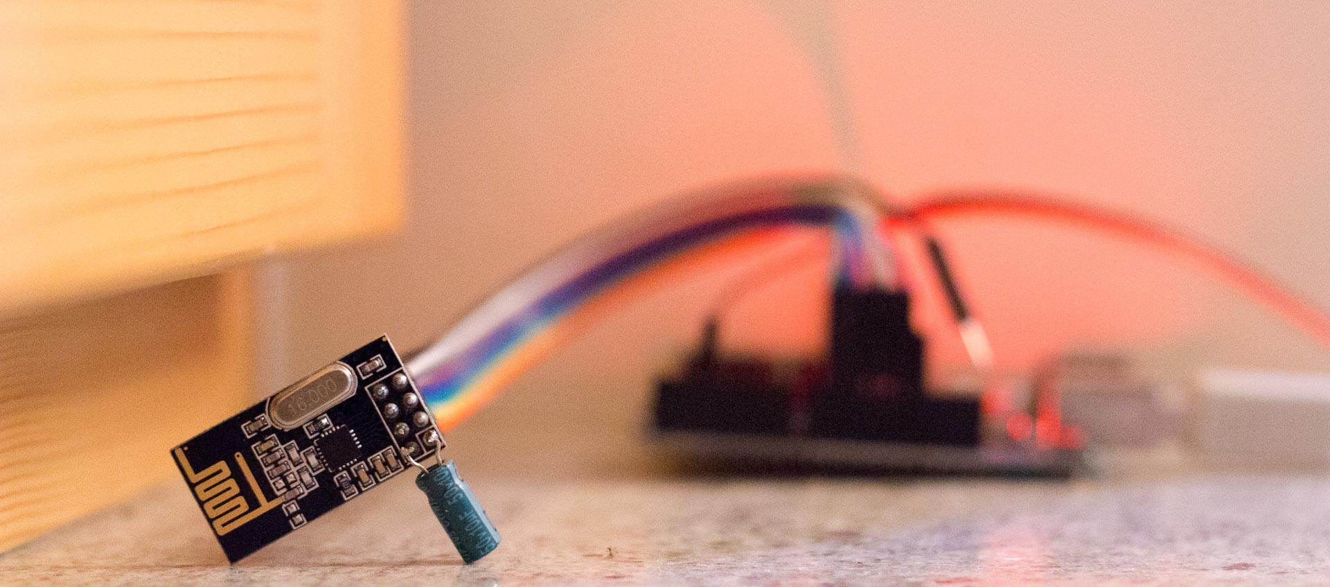
The first problem I encountered was getting arduinos to communicate using nRF24L01 modules. I read on forums that arduino might not provide enough current through 3.3V for powering nRF24L01 modules and I had to solder 10uF capacitor to Vcc and ground pins on the module.
You can check how to connect nRF24L01 module to Arduino here. I used this library for nRF24L01+: RF24 library.
After I got nRF24L01 modules to work, I wrote the arduino program that sends either value 1 or 2 to other Arduino, whenever push button was pressed or released. For the arduino used as receiver I wrote another program that receives data and switches GPIO pin state according to received value. Later I put data in array, so I could control multiple arduinos.
Arduino transmitter – the one connected to raspberry. You only need one.
 #include <SPI.h>
 #include <nRF24L01.h>
 #include <RF24.h>
 #define CE_PIN   9
 #define CSN_PIN 10


 const uint64_t pipe = 0xE8E8F0F0E1LL; // Define the transmit pipe
 RF24 radio(CE_PIN, CSN_PIN); // Create a Radio
 int state[2];
 int i = 5;


 //"button"
 const int buttonPin = 3;
 int buttonState = 0;


 //"button2"
 const int button2Pin = 2;
 int button2State = 0;


 void setup()
 {
    Serial.begin(9600);
   radio.begin();
   radio.openWritingPipe(pipe);

   //"button"
   pinMode(buttonPin, INPUT_PULLUP);

     //"button2"
   pinMode(button2Pin, INPUT_PULLUP);
 }


 void loop()
 {
     buttonState = digitalRead(buttonPin);
     if (!buttonState == HIGH) {
       state[0] = 2;
     }
     else {
       state[0] = 1;
     }

     button2State = digitalRead(button2Pin);
     if (!button2State == HIGH) {
       state[1] = 2;
     }
     else {
       state[1] = 1;
     }

    // radio send on command
        while (i > 1) {
           radio.write( state, sizeof(state));
           i = i - 1;
        }

   i = 5;
 }
Arduino receiver – connected to relay, which is switching the device on/off. You can use more of them.
 #include <SPI.h>
 #include <nRF24L01.h>
 #include <RF24.h>
 #define CE_PIN   9
 #define CSN_PIN 10


 const uint64_t pipe = 0xE8E8F0F0E1LL; // Define the transmit pipe
 RF24 radio(CE_PIN, CSN_PIN); // Create a Radio


 int state[2];
 int i = 1;


 void setup()
 {
   Serial.begin(9600);
   delay(1000);
   radio.begin();
   radio.openReadingPipe(1,pipe);
   radio.startListening();;


   //pins connected to relay module
   //You should use array if you're using more devices
   pinMode(2, OUTPUT);
   pinMode(3, OUTPUT);
   digitalWrite(2, HIGH);
   digitalWrite(3, HIGH);
 }


 void loop()
 {


   //module is constantly listening for data
   if ( radio.available() )
   {
     // Read the data payload until we've received everything
     bool done = false;
     while (!done)
     {
       // Fetch the data payload
       done = radio.read( state, sizeof(state) );


       //if you're using more remote devices, you should use loop
       if ( state[0] == 1 ) {
           digitalWrite(2, HIGH);
       }

       if ( state[0] == 2 ) {
           digitalWrite(2, LOW);
       }

       if ( state[1] == 1 ) {
           digitalWrite(3, HIGH);
       }

       if ( state[1] == 2 ) {
           digitalWrite(3, LOW);
       }

     }
   }
   else
   {
     i = i+1;
   }


   //I experienced some trouble when system was up for a long time and it stopped listening,
   //so in case of a problem, nRF24 module will restart.
   if (i > 50){
     i = 1;
     radio.stopListening();
     radio.begin();
     radio.openReadingPipe(1,pipe);
     radio.startListening();
     delay(1000);


   }


 }
I had to get Raspbery Pi and Arduino-transmitter to comunicate, so I replaced push button with transistor and raspberry pi circuit. Therefore when I used command for changing the GPIO state on raspberry pi – “gpio -g write 17 1”, The current would flow through base of the NPN transistor and hence closing the circuit on the arduino side, so arduino reads different state on gpio pin, causing it to send data to other arduino which controls the light.
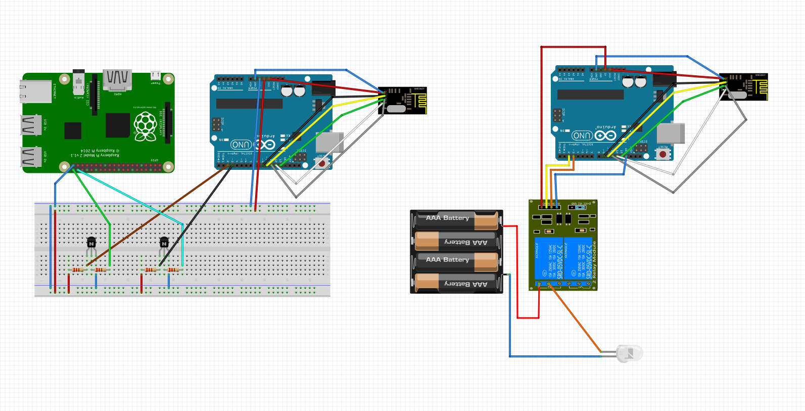
Here is my final diagram (both resistors are 10k):
Last step was to make web interface. First I wrote back-end in php for switching GPIO state of one pin on the Raspberry. It executed command to read current state of the GPIO pin and if the state was off, it executed same command as I used before to turn it on and vice versa. So whenever I reloaded the web page, the light turned on or off. I found some jQuerry mobile buttons on w3schools that I later used in my UI. I put gpio pins and names of devices in the array and used foreach loop so when I added another device – air conditioner, I only had to insert GPIO pin and name of the device in the array.
Web app code:
<?php
//specify gpio pins and names for devices
$gpioPins = array(
    17 => 'Big light',
    27 => 'Bedside light',
    21 => 'Small     ',
    20 => 'Air conditioner');

$i = 0;

//check current state for every gpio pin
foreach ($gpioPins as $pin => $name) {
    exec ( "gpio -g read $pin" , $status[$i] );
    $state[$i] = $status[$i][0];
//if button was pressed, change the gpio value of selected device (pin) depending on the previous state
    if ($_POST["$pin"] == "1") {
        system ( "gpio -g mode $pin out" );
        if ($state[$i] == 1) {
            system ("gpio -g write $pin 0");
            $state[$i] = 0;
        }elseif ($state[$i] == 0) {
            system ("gpio -g write $pin 1");
            $state[$i] = 1;
        }
    }
    $i++;
}
/* default gpio state of devices (i'm using pullup like switch for remote devices, so off state is "1")
im using three-way switch for big light, so i can turn on/off light from normal switch too,
but then I can't monitor on/off state of the light using this setup */
$defaultState = array($status[0],0,1,1);
?>
<!DOCTYPE HTML>
<html>
    <head>
        <title>Remote</title>
        <meta name="viewport" content="width=device-width, initial-scale=1">
        <link rel="stylesheet" href="http://code.jquery.com/mobile/1.4.5/jquery.mobile-1.4.5.min.css">
        <script src="http://code.jquery.com/jquery-1.11.3.min.js"></script>
        <script src="http://code.jquery.com/mobile/1.4.5/jquery.mobile-1.4.5.min.js"></script>
        <meta charset="UTF-8">
    </head>
    <body>
        <div data-role="page" id="pageone">
            <?php $i=0; foreach ($gpioPins as $pin => $name) { ?>
            <div data-role="header">
                <h1><?php echo $name; ?></h1>
            </div>
            <div data-role="main" class="ui-content">
                <form  id="test" name="test" action="index.php" method="post">
                    <input type="hidden" name="<?php echo $pin; ?>" value="1"></input>
                    <div class="ui-btn ui-input-btn <?php if($state[$i] == $defaultState[$i]) {print("ui-btn-b");} ?> ">
                        <?php if($state[$i] == $defaultState[$i]) {print("Turn Off");} else {print("Turn On");} ?>
                        <input type="submit" data-corners="false" data-enhanced="true" value="On/Off"></input>
                    </div>
                </form>
            </div>
            <?php $i++; } ?>
        </div>
    </body>
</html>
Video demo:
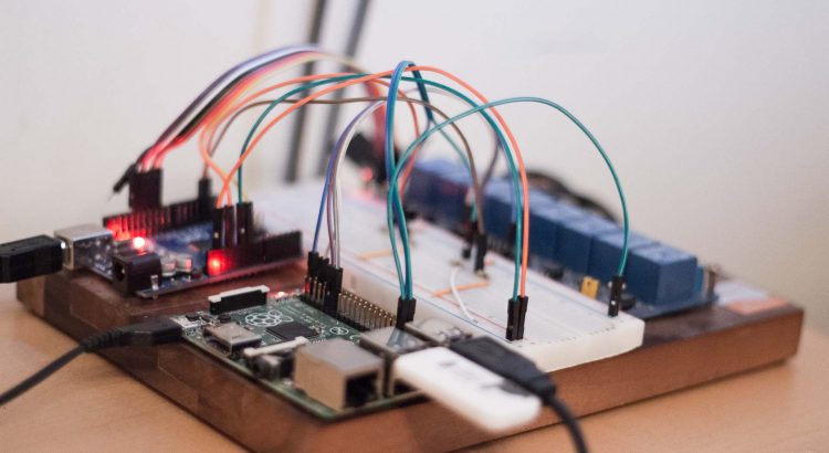
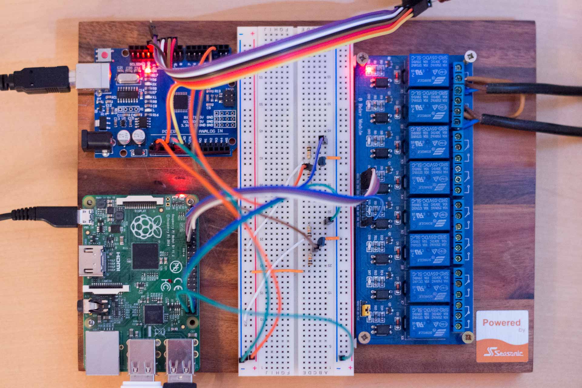
Here is the picture of the final transmitter side setup. I have two GPIO pins on Raspberry connected to relay next to it and two connected to arduino through transistor circuit. Oh, and Aruino is powered by Raspberry pi’s USB.
If you are doing this project yourself, make sure you have installed apache2, php and wiringPi on your Raspberry Pi:
sudo apt-get install apache2 php5
git clone git://git.drogon.net/wiringPi
cd wiringPi
git pull origin
cd wiringPi
./build

